Understanding the Ins and Outs of RF Connectors
von Sam Utley | Aktualisiert: 03/30/2016 | Kommentare: 4

While you may have no problem identifying which standard polarity RF connectors are pin (male) or socket (female), do you find it difficult to identify the gender of reverse polarity connectors? If so, don’t worry. You are certainly not alone. In addition to the gender issue, it’s easy to get confused by the many different types of RF connectors used with Campbell Scientific equipment. When you try to mate your devices, you may sometimes wonder which connector type you have and which connector type you need.
In this short article, I’ll explain the difference between pin (male) and socket (female) RF connectors in terms of their polarity—standard or reverse (RP). I’ll also include a number of images to help you identify the various types of connectors we commonly use.
Some Background
RF (radio frequency) connectors are commonly used on many of our products, such as radios, surge protectors, enclosures, coaxial cables, and antennas. These connectors, however, come in a variety of types. The most common connector types are these:
- Type N
- UHF (PL259)
- TNC
- Reverse Polarity TNC (RPTNC)
- BNC
- SMA
- Reverse Polarity SMA (RPSMA)
You might wonder how reverse polarity connector types became so common. This is a result of the FCC (Federal Communications Commission) introducing regulations for low-power non-licensed transmitters, which are commonly known as Part 15 transmitters. Twenty years ago, the FCC in the U.S. introduced the practice of using “unique connectors” (that is, connectors that are not a standard part at electronics stores). The theory behind this practice was that it would be difficult for someone to purchase and attach a non-certified antenna to a device.
In the past two decades, however, the practice of using “unique connectors” has become commonplace, which has led to the proliferation of reverse polarity connector types. So, let’s sort them out.
Gender and Polarity
When you’re trying to identify pin (male) and socket (female) connectors, you may find it helpful to keep in mind the following:
- When mating two connectors, it is important to ensure that both connectors have the same polarity. For example, both should be RPSMA.
- Typically, RF plugs are pin (male), and the threads are on the inside of the shell.
- Typically, RF jacks are socket (female), and the threads are on the outside of the shell.
- The shell of a plug (male) typically covers the shell of a jacket (female).
Building off of these concepts, here are some more helpful descriptions:
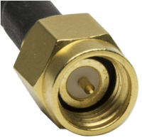
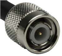
- A standard polarity plug (male) has a center pin that sticks out from the middle, and the plug’s shell has threads on the inside. Here we have shown an SMA plug, typically found on the end of a coaxial cable that connects to products such as cellular gateways or GPS receivers.
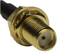
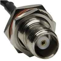
- A standard polarity jack (female) has a socket in the middle designed to receive the pin from the plug (male), and the jack’s shell has threads on the outside. Here we have shown an SMA jack, typically found on a radio such as a cellular gateway or GPS receiver.
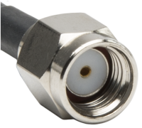
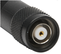
- A reverse polarity plug (male) has a socket in the middle designed to receive the pin from the jack (female) connector, and the plug’s shell has threads on the inside. Here we have shown an RPSMA plug, typically found on the end of a coaxial cable that connects to products such as the RF451, RF407-series, and CR6-WIFI.
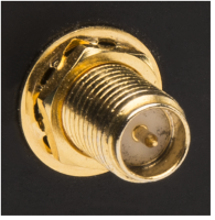
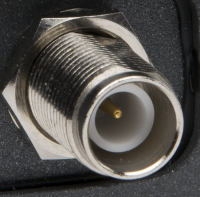
- A reverse polarity jack (female) has a center pin that sticks out from the middle, and the jack’s shell has threads on the outside. Here we have shown an RPSMA jack, typically found on a radio such as our 900 MHz spread-spectrum and Wi-Fi devices.
Remember:
- A standard polarity jack (female) has a socket, whereas a reverse polarity jack (female) has a pin.
- A standard polarity plug (male) has a pin, whereas a reverse polarity plug (male) has a socket.
Connector Types and Genders
The following table identifies for you the various types of connectors we commonly use and their genders:
| Connector Type | Plug (Male) | Jack (Female) |
|
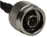
Type N |
(pin with threads inside) |
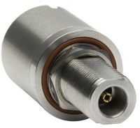
(socket with threads outside) |
|
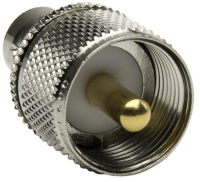
UHF (PL259) |
(pin with threads inside) |
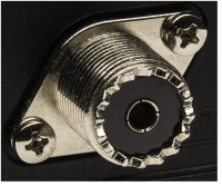
(socket with threads outside) |
|
TNC |
(pin with threads inside) |
(socket with threads outside) |
|
Reverse Polarity TNC (RPTNC) |
(socket with threads inside) |
(pin with threads outside) |
|
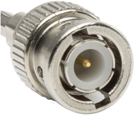
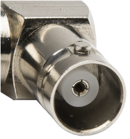
BNC |
(pin with threads inside) |
(socket with threads outside) |
|
SMA |
(pin with threads inside) |
(socket with threads outside) |
|
Reverse Polarity SMA (RPSMA) |
(socket with threads inside) |
(pin with threads outside) |
I hope the descriptions and images have helped you understand the differences between the connector types and the interplay of polarity and gender.
Stay connected (with your devices and us), and post your comments below.


Über den Author
 Sam Utley was the Principal Product Manager and previously the Vice President of Research and Development at Campbell Scientific, Inc. His deep understanding and appreciation for Campbell Scientific customers and their need for measurement and control solutions developed from his experience as a Campbell Scientific customer, sales and support specialist, and product manager. Sam is a University of Georgia Biological and Agricultural Engineer graduate.
Kommentare
Duncan | 03/30/2016 at 10:10 AM
Sam,very good article very informative. I would see something about signal attenuation contributors and explanation of dBd values.
Duncan Maciver
Sam | 03/30/2016 at 11:01 AM
Duncan,
Thank you for reading, and thank you for the feedback. It gives me a good idea for another article.
Engineering_Technician | 10/23/2018 at 09:32 AM
Wow! I love this article. It explains and breaks down the RF connectors so well. Is it okay if I use this to help train new employees on RF connectors? Also, I really wish you had more articles like this!
Sam | 10/29/2018 at 01:48 PM
Engineering_Technician,
Thank you very much for the feedback. We would love for you to use this material to help others understand the "ins" and "outs" of RF connectors. Please feel free to draw on the concepts. If you republish the materials, please make sure to cite your source. Regarding more articles, please don't hesitate to nominate some topics you would like to learn more about.
Best Regards
Please log in or register to comment.