4 Tips to Successfully Run an MD485 Network with Extreme Cable Lengths
von Andrew Sandford | Aktualisiert: 12/23/2015 | Kommentare: 0
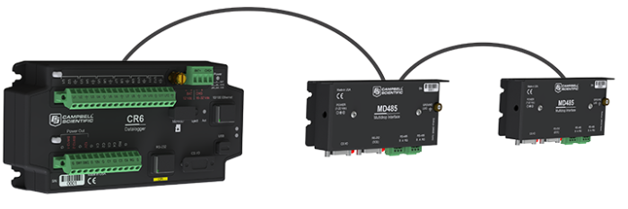
Do you have a network of devices, connected using MD485 interfaces, so spread out that extremely long cables are required? Are you worried that the distances, and resultant cable lengths, may be causing communication problems? In this brief article, we’ll look at four tips that can help ensure your MD485 network operates correctly.
MD485 networks use RS-485 communications hardware for which the total maximum length is quoted as “up to” 1,200 meters (4,000 feet), with potentially up to 256 devices on the network. As you might suspect, the words “up to” really do indicate that you may not achieve the limits quoted in practice—or at least without careful design.
So whilst setting up a small network with short cables is a simple task, as the network size grows, you can run into problems with data corruption that result in lots of retries and delays. Sometimes extending the network can “push it over the edge,” and it will stop working altogether.
To help you set up a reliable network, here are some tips to follow.
#1 – Use a high-quality cable and a simple linear layout
Ensure that you are using a twisted pair, high-quality cable. Ideally, the cable should be shielded, with the shield connected to ground at one end. Campbell Scientific offers a suitable cable (CABLE2TP), but you can also use existing structured wiring such as CAT5/6 cable. Whichever type of cable you use, make sure that the A/B wires used for the data connection are from the same pair of conductors in the cable. Also, it is best to design a network with a linear daisy chain of devices rather than a star arrangement.
#2 – Check the resistive/reference ground connections
Make sure that all of the resistive/reference ground terminals between your MD485 interfaces are connected together using an extra conductor in the cable. Prior to doing this, you can check that the voltage difference between the grounds of the different MD485 interfaces are not too large. If the voltage differences are too large, this can prevent communication and could even be hazardous.
To check the voltage difference, disconnect the ground-referencing wire temporarily and then use a voltmeter to measure the voltage between the end of the wire (connected to the rest of the network) and the MD485 reference ground. If the potential is more than a few volts, review the grounding of the different systems. If the potentials cannot be brought closer, consider adding a third-party RS-485 isolating repeater.
#3 – Reduce the baud rate
If you have had to use lower-grade cable and the cable runs are long, you can try reducing the baud rate over the RS-485 cable itself to 38.4 kb/s or slower. If this does not help and the activity LEDs at remote stations do not light when data is transmitted from the other end, you may have to boost the RS-485 signals. You can do this by splitting the network in half and adding some type of repeater. The repeater could be two MD485 interfaces connected back-to-back via their RS-232 ports, or you could use two MD485 interfaces (with different SDC addresses) that are connected to one datalogger set to act as a router. Another option is to use a third-party RS-485 repeater.
#4 – Install termination resistors
If the activity LEDs flash as expected but your data is getting corrupted, try installing a 120 ohm termination resistor across the A/B lines at each of the two extreme ends of the network. This modification reduces the reflections of signals in the cable and also helps eliminate some types of noise. (These resistors are rarely required for most MD485 networks, and fitting them can increase power use slightly, but their use is considered to be good practice by RS-485 network designers.)
Conclusion
Making MD485 networks work well with extreme cable lengths can be tricky. I hope these tips help make the job easier for you.
Tip: You can apply the principles outlined in this article’s four tips when you make RS-485 connections to a CR6 datalogger, via its control ports, or when you connect sensors to a datalogger using an SDM-SIO1 module.
If you have any questions or comments, please feel free to post them below.


Über den Author
 Dr. Andrew Sandford is the Director of Research and Development at Campbell Scientific Limited in the United Kingdom. Andrew has been with Campbell Scientific Ltd for more than 30 years and leads a team of R&D engineers that has been responsible for the design and delivery of a wide variety of Campbell Scientific products.
Kommentare
Please log in or register to comment.