keine Wartung notwendig


Überblick
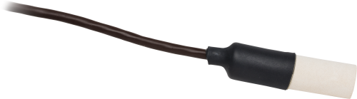
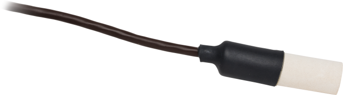
Der 229 ist ein Sensor der das Bodenwasserpotential von 0,1 bis 10 bar misst. Zum Anschluss ist entweder ein CE4 oder ein CE8 Anregunsstrommodul notwendig. Dieses Modul wird von einem Campbell-Logger kontrolliert, der Messwert aufgenommen und das Matrixpotential berechnet.
Lesen Sie mehrFunktionen und Vorteile
- Compatible with most Campbell Scientific data loggers
- Measures a wide range of matric potential
- Measurements not affected by salts in the soil
- Long lasting, with no maintenance required
- Compatible with AM16/32-series multiplexers, allowing measurement of multiple sensors
Bilder

Technische Beschreibung
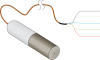
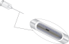
The 229 Water Matric Potential Sensor consists of a heating element and thermocouple placed in epoxy in a hypodermic needle, which is encased in a porous ceramic matrix.
To calculate soil water matric potential, a CE4 or CE8 current excitation module applies a 50 mA current to the 229's heating element, and the 229's thermocouple measures the temperature rise. The magnitude of the temperature rise varies according to the amount of water in the porous ceramic matrix, which changes as the surrounding soil wets and dries. Soil water matric potential is determined by applying a second-order polynomial equation to the temperature rise. Users must individually calibrate each of their 229 sensors in the soil type in which the sensors will reside.
A reference temperature measurement is required for the 229's thermocouple measurement. The temperature sensor built into many of our dataloggers' wiring panel typically provides this measurement.
Kompatibel mit
Please note: The following shows notable compatibility information. It is not a comprehensive list of all compatible products.
Datenlogger
| Product | Compatible | Note |
|---|---|---|
| CR1000 (retired) | ||
| CR1000X (retired) | ||
| CR300 (retired) | ||
| CR3000 | ||
| CR310 | ||
| CR350 | ||
| CR6 | ||
| CR800 (retired) | ||
| CR850 (retired) |
Additional Compatibility Information
Current Excitation Modules
Either a CE4 or CE8 current excitation module is required to provide a constant current to the heating element of the 229. The CE4 and CE8 differ only in the number of 229 sensors to which they source current. The CE4 sources current for up to four 229s, and the CE8 sources current for up to eight. Both modules require a 12 Vdc power source.
Multiplexers
In applications that require more sensors, the output(s) of the CE4 or CE8 can be connected to as many AM16/32-series multiplexers as there are outputs, greatly expanding system capacity. If using multiplexers, the user should be aware that switching currents of greater than 30 mA will degrade the contact surfaces of the mechanical relays. Therefore the data logger should be programmed to turn off the current excitation module before switching multiplexer channels in order to protect the multiplexer relays.
Data Logger Considerations
One differential channel and one current excitation channel per probe are required. Each CE4 or CE8 current excitation module requires one data logger control port.
Programming
The 229 is measured by a sequence of data logger instructions where the thermocouple is measured at 0 s, 1 s, and 30 s, while a 50 mA current is applied to the heating element. This current is supplied by the CE4 or CE8 current excitation module. The rise in temperature during heating is related to the soil water matric potential.
Reference Temperature Measurement
A reference temperature measurement is required. Options for measuring the reference temperature include:
- Thermistor built into the CR800, CR850, CR1000, CR3000, or CR5000 wiring panel
- PRT built into the wiring panel of the CR9050 or
- CR9051E input module for the CR9000X Measurement and Control Datalogger
- PRT built into the wiring panel of the CR723T input card for the CR7 Measurement and Control Datalogger
- CR10XTCR thermistor that connects to the CR10X wiring panel
Spezifikationen
| Operating Temperature Range | -5° to +30°C |
| Normal Environmental Temperature Range | -40° to +70°C |
| Measurement Range | -10 to -2500 kPa |
| Measurement Time | 30 s (typical) |
| Thermocouple Type | Copper/constantan (type T) |
| Heater Resistance | ~34 Ω |
| Resolution | ~1 kPa (at matric potentials < -100 kPa) |
| Diameter | 1.5 cm (0.6 in.) |
| Length | 6.0 cm (2.4 in.) |
| Cable Weight | ~23 g/m (0.25 oz/ft) |
| Sensor Weight | 10 g (0.35 oz) |
Dokumente
FAQs für
Number of FAQs related to 229: 7
Alle anzeigenWenige anzeigen
-
For details and sample programs, see the "Example Programs" section of the 229-L manual.
-
Very low values for dT, especially negative values, indicate that the 229-L sensor is not heating during the measurement time. The most likely causes are damage to the heater wires, one or more loose wires, or a failure of the constant current excitation module.
The first check to make is of the heater wire itself. With an ohmmeter, measure the resistance between the black and green wires on the 229-L. The resistance should read approximately 33 to 36 ohm. An off-scale or infinite reading indicates a break in the heater wire. A low reading could indicate a short in the heater wire. In both of those cases, the fix would be to dig up the sensor wire and examine it for damage.
The next check is to make sure that there are good electrical connections in the following locations:
- where the black and green sensor wires connect to the constant current interface or to a multiplexer
- where the multiplexer common wires connect to the constant current interface
- where the constant current interface connects to the datalogger 12V, G, and control port
Each of those wires should have approximately a quarter inch of bare copper securely connected to its terminal.
Finally, the CE4 or CE8 constant-current module can be checked with a multimeter to make sure it is putting out 50 mA. Measure the voltage between the 12V and ground terminal screws to make sure that the constant current module is receiving power from the datalogger. Next, temporarily move the wire connecting the datalogger control port with the CTRL channel to a 5 V channel on the datalogger to force the module to be on all the time, so that the current output can be measured. Set the multimeter to measure milliamps, and measure the current. It should be 50 mA ± 1 mA. If the current output is outside that range, the constant current module needs to be repaired or replaced.
-
At this time, Campbell Scientific does not offer a calibration service for the 229-L. There are companies that offer this service. Contact Campbell Scientific for details.
-
The heater wire itself should read around 33 ohm for resistance, but the green and black wires connected to the heater wire will also add resistance to the reading. The longer the sensor cable, the greater the resistance reading will be. Therefore, readings of 37 to 48 ohm are within the normal range. A resistance reading of infinity or of less than 33 ohm would be caused by a break or short in the sensor cable and would be cause for concern.
-
If all the errors were summed in a worst case scenario, the thermocouple accuracy would be ±0.5°C. For an extended discussion about thermocouple measurements, refer to the "Thermocouple Measurements" section in the data logger manual.
-
The heating element is made of Evanohm wire. The element is encased in epoxy inside a stainless-steel hypodermic needle and is not exposed to the corrosive environment. Therefore, that part of the sensor should not fail in five years. However, the sensor cable and the ceramic matrix might suffer damage after being exposed to a corrosive environment for five years.
-
For details, see the "Calibration" section of the 229-L manual.
Anwendungsbeispiele
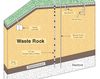
Acid Rock Drainage (ARD) problems associated with hard rock metal mining are one of the......lesen Sie mehr