
Stabile, robuste und genaue PAR-Messungen bei unterschiedlichen Lichtquellen


Überblick
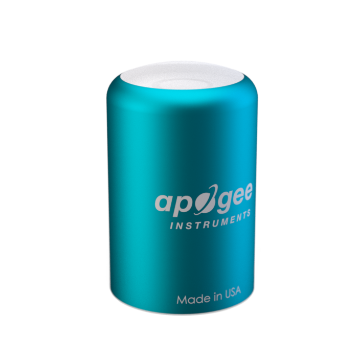
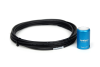
Der CS310 ist ein analoger Qantumsensor mit einem Ausgangssignal von 0 bis 40 mV. Der Sensor basiert auf einer eine blau-verstärkte Silikonphotodiode und speziellen optischen Filtern in einem robusten, selbstreinigendem Gehäuse (anodisiertes Aluminum mit Acryl-Diffuser). Typisches Einsatzgebiet sind PPFD-Messungen über Pflanzenbeständen im Freiland, Gewächshäusern und Klimakammern sowie zur Messung von reflektierten oder unter dem Bestand auftretenden (transmitted) PPFD in denselben Umgebungen.
Lesen Sie mehrFunktionen und Vorteile
- Full-spectrum quantum sensor with a spectral range of 389 to 692 nm (±5 nm)
- Accurate measurements under all light sources including Light Emitting Diodes (LEDs)
- Dome-shaped anodized aluminum body designed to be rugged and self-cleaning for a longer life and lower maintenance
- IP68 rated connector provides extra assurance in wet and harsh environments
- Sensor head detachable from the cable with a marine-grade 316-L stainless-steel connector for fast, easy servicing
- Factory calibration data stored in the sensor so no sensor-specific calibration coefficients required for an accurate measurement
- Each sensor carefully calibrated in controlled conditions and traceable to NIST reference standards
- Four-year manufacturer warranty
Bilder
Technische Beschreibung
Radiation that drives photosynthesis is called photosynthetically active radiation (PAR) and is typically defined as total radiation across a range of 400 to 700 nm. PAR is often expressed as photosynthetic photon flux density (PPFD): photon flux in units of micromoles per square metre per second (µmol m-2 s-1, equal to microEinsteins per square meter per second) summed from 400 to 700 nm (total number of photons from 400 to 700 nm). While Einsteins and micromoles are equal (one Einstein = one mole of photons), the Einstein is not an SI unit, so expressing PPFD as µmol m-2 s-1 is preferred.
Sensors that measure PPFD are often called quantum sensors due to the quantized nature of radiation. A quantum refers to the minimum quantity of radiation (one photon) involved in physical interactions (for example, absorption by photosynthetic pigments). In other words, one photon is a single quantum of radiation.
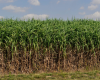
Typical applications of quantum sensors include incoming PPFD measurement over plant canopies in outdoor environments or in greenhouses and growth chambers, and reflected or under-canopy (transmitted) PPFD measurement in the same environments.
The CS310 quantum sensor consists of a cast acrylic diffuser (filter), photodiode, and signal processing circuitry mounted in an anodized aluminium housing with a cable to connect the sensor to a measurement device. The CS310 quantum sensor is designed for continuous PPFD measurement in indoor or outdoor environments. It outputs an analogue signal that is directly proportional to PPFD. The analogue signal from the sensor is directly proportional to radiation incident on a planar surface (does not have to be horizontal), where the radiation emanates from all angles of a hemisphere.
References
- Federer, C.A., and C.B. Tanner, 1966. Sensors for measuring light available for photosynthesis. Ecology 47:654-657.
- Ross, J., and M. Sulev, 2000. Sources of errors in measurements of PAR. Agricultural and Forest Meteorology 100:103-125.
- Federer, C.A., and C.B. Tanner, 1966. Sensors for measuring light available for photosynthesis. Ecology 47:654-657.
- Inada, K., 1976. Action spectra for photosynthesis in higher plants. Plant and Cell Physiology 17:355-365.
- McCree, K.J., 1972a. The action spectrum, absorptance and quantum yield of photosynthesis in crop plants. Agricultural Meteorology 9:191-216.
- McCree, K.J., 1972b. Test of current definitions of photosynthetically active radiation against leaf photosynthesis data. Agricultural Meteorology 10:443-453.
- Sager, J.C., W.O. Smith, J.L. Edwards, and K.L. Cyr, 1988. Photosynthetic efficiency and phytochrome photoequilibria determination using spectral data. Transactions of the ASAE 31:1882-1889.
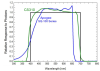
Spectral Response
Refer to the mean spectral response graph in the Images section of the web page. The graph shows the mean spectral response measurements of six replicate Apogee SQ100 and CS310 quantum sensors. Spectral response measurements were made at 10 nm increments across a wavelength range of 300 to 800 nm in a monochromator with an attached electric light source. Measured spectral data from each quantum sensor were normalized by the measured spectral response of the monochromator/electric light combination, which was measured with a spectroradiometer.
Kompatibel mit
Please note: The following shows notable compatibility information. It is not a comprehensive list of all compatible products.
Datenlogger
| Product | Compatible | Note |
|---|---|---|
| CR1000 (retired) | ||
| CR1000X (retired) | ||
| CR300 (retired) | ||
| CR3000 | ||
| CR310 | ||
| CR350 | ||
| CR6 | ||
| CR800 (retired) | ||
| CR850 (retired) |
Additional Compatibility Information
Mounting
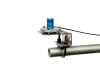
Accurate measurements require the sensor to be leveled using a 18356 leveling fixture. This leveling fixture incorporates a bubble level and three leveling screws. The 18356 mounts to a crossarm using the CM225 mounting stand or 015ARM. The CS310 should be mounted away from all obstructions and reflective surfaces that might adversely affect the measurement.
Spezifikationen
| Sensor | Blue-enhanced silicon photodiode and custom optical filters |
| Measurement Description | Measures photosynthetic photon flux density (PPFD) in both natural and artificial light |
| Power Supply | Self-powered |
| Sensitivity | 0.01 mV per µmol m-2 s-1 |
| Calibration Factor (Reciprocal of Sensitivity) | 100.0 µmol m-2 s-1 per mV |
| Calibration Uncertainty | ±5% (for daily total radiation) |
| Calibrated Output Range | 0 to 40 mV |
| Measurement Range | 0 to 4000 µmol m-2 s-1 |
| Measurement Repeatability | < 1% (up to 4000 μmol m-2 s-1) |
| Long-Term Drift | < 2% per year |
| Non-Linearity | < 1% (up to 4000 µmol m-2 s-1) |
| Response Time | < 1 ms |
| Field of View (FOV) | 180° |
| Spectral Range | 389 to 692 nm ±5 nm (wavelengths where response is greater than 50% of maximum) |
| Spectral Selectivity | < 10% from 412 to 682 nm ±5 nm |
| Directional (Cosine) Response | ±5% (at 75° zenith angle) |
| Azimuth Error | < 0.5% |
| Tilt Error | < 0.5% |
| Temperature Response | -0.11 ±0.04% per °C |
| Uncertainty in Daily Total | < 5% |
| Detector | Blue-enhanced silicon photodiode |
| Housing | Anodized aluminum body with acrylic diffuser |
| IP Rating | IP68 |
| Operating Temperature Range | -40° to +70°C |
| Operating Environment | 0 to 100% relative humidity |
| Cable |
5 m of shielded, twisted-pair wire Additional cable available in multiples of 5 m; Santoprene rubber jacket (high water resistance, high UV stability, flexibility in cold conditions); pigtail lead wires |
| Warranty | 4 years (against defects in materials and workmanship) |
| Diameter | 2.4 cm (0.9 in.) |
| Height | 3.5 cm (1.4 in.) |
| Weight | 100 g with 5 m of lead wire (3.53 oz with 16.4 ft of lead wire) |
Dokumente
Broschüren Produkte
Handbücher
Technische Artikel
Übereinstimmung mit Richtlinien u. Vorschriften
FAQs für
Number of FAQs related to CS310: 3
Alle anzeigenWenige anzeigen
-
The leveling base provides physical stability and helps ensure the sensor is leveled correctly. It is not recommended to use the sensor without the base. The sensor mounts to the base with an included bolt. However, a user-supplied plate with a hole drilled in it could be used instead to accept the sensor’s mounting bolt.
-
The Clear Sky Calculator (www.clearskycalculator.com) can be used to determine the need for quantum sensor recalibration. It determines PPFD incident on a horizontal surface at any time of day at any location in the world. It is most accurate when used near solar noon in spring and summer months, where accuracy over multiple clear and unpolluted days is estimated to be ±4% in all climates and locations around the world. For best accuracy, the sky must be completely clear, as reflected radiation from clouds causes incoming radiation to increase above the value predicted by the clear sky calculator. Measured values of PPFD can exceed values predicted by the Clear Sky Calculator due to reflection from the sides and edges of clouds. This reflection increases the incoming radiation. The influence of high clouds typically shows up as spikes above clear sky values, not a constant offset greater than clear sky values.
To determine recalibration need, input site conditions into the calculator and compare PPFD measurements to calculated PPFD values for a clear sky. If sensor PPFD measurements over multiple days near solar noon are consistently different than calculated values (by more than 6%), the sensor should be cleaned and re-leveled. If PPFD measurements are still different after a second test, contact Campbell Scientific for an RMA to get the sensor recalibrated.
Anwendungsbeispiele
Overview In the fight against climate change, innovative solutions are emerging to address the global challenge......lesen Sie mehr