Interner Signalverstärker minimiert Inteferenzen


Überblick
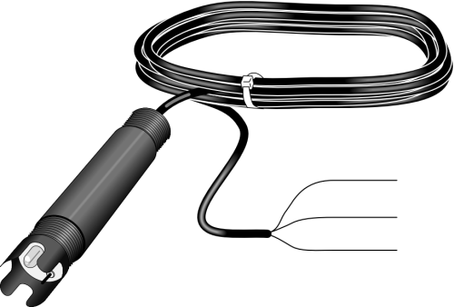
Der CSIM11 misst den gesamten pH-Bereich von Flüssigkeiten. Er kann im Wasser versenkt werden oder in Tanks, Rohrleitungen und offenen Kanälen eingesetzt werden. Der CSIM11 ist nicht für Anwendungen unter Druck ausgelegt, mehr als 30 psig sind nicht möglich.
Wenn Sie einen Sensor für Anwendungen in Rohren unter Druck brauchen, kontaktieren Sie Campbell Scientific.
Lesen Sie mehrFunktionen und Vorteile
- Internal amplifier boosts the signal, decreasing signal interference
- Titanium ground rod runs inside the outer body to eliminate ground loop errors
- Compatible with most Campbell Scientific data loggers
- Porous polytetrafluoroethylene (PTFE) liquid junction is less susceptible to clogging as compared to conventional reference junctions
- Plunger-style pH glass electrode allowing the probe to be mounted at any angle
Bilder

Zugehörige Produkte


Technische Beschreibung
The CSIM11 has a plunger-style pH glass electrode that allows the CSIM11 to be mounted at any angle. Its porous polytetrafluoroethylene (PTFE) liquid junction is less susceptible to clogging as compared to conventional reference junctions.
A titanium ground rod runs inside the PPS outer body to eliminate ground loop errors. An internal amplifier boosts the signal, decreasing signal interference. The amplifier is powered by two internal lithium batteries, and thus does not require any power from the datalogger. These batteries are designed to last the lifetime of the probe.
The reference solutions and bulb configuration are optimized for natural water applications. Alternate reference solutions and bulb configurations are available. Contact Campbell Scientific for pricing and availability.
Note: The CSIM11 uses glass bulb technology which has a life expectancy of around 6 months to 2 years, depending on the conditions of the water.
Kompatibel mit
Please note: The following shows notable compatibility information. It is not a comprehensive list of all compatible products.
Datenlogger
| Product | Compatible | Note |
|---|---|---|
| CR1000 (retired) | ||
| CR1000X (retired) | ||
| CR300 (retired) | ||
| CR3000 | ||
| CR310 | ||
| CR350 | ||
| CR6 | ||
| CR800 (retired) | ||
| CR850 (retired) |
Additional Compatibility Information
Data Logger Considerations
The CSIM11 requires a differential analog input channel.
Spezifikationen
| pH Range | 0 to 14 |
| Zero Potential | 7.0 pH ±0.2 pH |
| Sodium Error | < 0.05 pH (in 0.1 Molar Na+ ion at 12.8 pH) |
| Output | ±59 mV/pH unit |
| Pressure Range | 0 to 30 psig |
| Accuracy | ±0.1% (over full range) |
| Impedance | < 1 Mohm (@ 25°C) |
| Reference Cell | Single Junction KCl/AgCl |
| Body Material | ABS |
| Wetted Materials | ABS, polytetrafluoroethylene (PTFE), Viton, glass, titanium |
| Cable Jacket Material | Polyurethane |
| Response Time | 95% of reading (in 10 s) |
| Drift | < 2 mV per week |
| Internal Lithium Battery Lifetime | 5 y (life of probe) |
| Diameter | 3.0 cm (1.2 in.) |
| Length | 17.8 cm (7.0 in.) |
| Weight | 0.5 kg (1 lb) with 4.57-m (15-ft) cable |
Dokumente
Handbücher
FAQs für
Number of FAQs related to CSIM11-L: 5
Alle anzeigenWenige anzeigen
-
Silver is the best electrical conductor of all the metals because it has the lowest electrical resistance. The silver wire, coated in silver chloride, is relatively insensitive to changes in temperature.
-
A reference electrode can become contaminated when poisoning ions such as lead, iron, chrome, cyanide, or sulfide enter the reference electrode and react either with the silver wire or with the electrolyte solution.
The contamination may not become apparent until the silver-chloride coating is completely dissolved and the electrical potential from the reference electrode has changed greatly. If this occurs, the reference electrode must be replaced.
-
Cleaning and/or calibration may be required when the measurements are scattered, drifting occurs, or there is physical evidence of fouling. Measurements for pH must be monitored regularly to check for scattering. However, just because the results are scattered does not necessarily indicate the need for an adjustment. For example, there may be a change in the water source that causes the scattering. As a sensor ages, however, the scattering of the measured values tends to increase.
To check the performance of a pH sensor, use it to measure a buffer solution in the correct range. If the value returned is within the specified range, the sensor does not need to be calibrated.
-
In the event that both alkaline and acidic sample solutions are measured using a single pH sensor, a multipoint calibration is done using three buffer solutions. As in the two-point calibration, the first buffer solution has a 7.0 pH. The second buffer solution should be near in pH value to either the acidic or alkaline sample solution, and the third buffer solution should be near in pH value to the other.
-
The recommended calibration method listed in a specific pH sensor’s instruction manual should be followed to guarantee the best results. Calibration must be performed correctly to ensure accurate and repeatable measurements. Before performing calibration, the pH sensor should be cleaned.
Calibration is commonly done using a known-value pH solution called a buffer. The buffer solution is formulated to resist pH changes caused by external contaminants. However, the pH of the buffer solution changes as the temperature changes. To compensate for this, manufacturers list the pH of the buffer solution at various temperatures on the buffer solution’s bottle so that the correct value for calibration is selected.
The most common calibration method is a two-point calibration using two buffer solutions. Each buffer solution has known and accurate pH values at different temperatures. The buffers used should be based on the normal measurement range that the pH sensor operates in for the application. One buffer solution should have a 7.0 pH. The second buffer solution should have a pH that is near the expected pH value of the sample solution.