Überblick
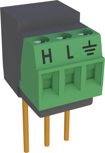
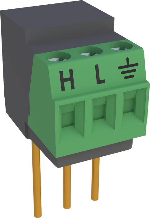
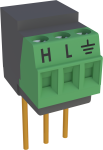
The VDIV10:1 uses precision resistor networks to bring sensors with high output voltages into the datalogger’s common mode range, allowing the datalogger to measure the sensor. The VDIV10:1 divides the sensor’s signal voltage by a factor of ten.
Lesen Sie mehrFunktionen und Vorteile
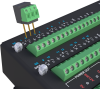
- Connects directly into data logger input terminals
- Easy to install or remove
- Low power consumption
Bilder
Zugehörige Produkte
Technische Beschreibung
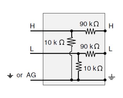
The VDIV10:1 contains a 90 kΩ resistor and a 10 kΩ resistor. Both resistors have a ratio tolerance of ±0.02%.
The maximum input voltage into the VDIV10:1 should not exceed ±50 V. Increased input settling time may be necessary to accommodate the relatively high resistance of the voltage divider.
Schematic for VDIV10:1
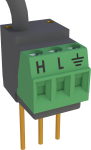
Hookup for one sensor measured differentially

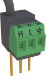
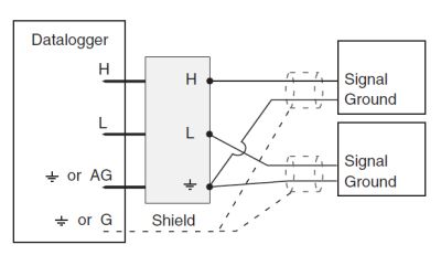
Hookup for two single-ended sensor measurements
Kompatibel mit
Please note: The following shows notable compatibility information. It is not a comprehensive list of all compatible products.
Datenlogger
| Product | Compatible | Note |
|---|---|---|
| CR1000 (retired) | ||
| CR200X (retired) | User-modifications are required to use the VDIV10:1 with the CR200X series. Contact Campbell Scientific for more information. | |
| CR216X (retired) | User-modifications are required to use the VDIV10:1 with the CR200X series. Contact Campbell Scientific for more information. | |
| CR300 (retired) | ||
| CR3000 | ||
| CR310 | ||
| CR350 | ||
| CR5000 (retired) | ||
| CR6 | ||
| CR800 (retired) | ||
| CR850 (retired) | ||
| CR9000X (retired) | Compatible CR9000X modules are the CR9050 and the CR9052; the CR9051 is partially compatible. |
Additional Compatibility Information
Data Logger Considerations
The VDIV10:1 uses two adjacent single-ended analog inputs (one differential channel); an adjacent analog ground channel accepts the "ground prong" of the VDIV10:1. Not all data logger terminal strips have this sequence on all channels, so please check your data logger's wiring panel to confirm channel assignments, especially if you plan to use multiple terminal input modules.
Please note that if a CR10X will be used to measure thermocouples in the same application, newer CR10X Wiring Panels and the CR10XTCR Reference Thermistor (with its accompanying thermocouple cover) are deep enough to cover the data logger input channels with a VDIV10:1 attached; older CR10TCRs are not deep enough.
Programming
The VDIV10:1 is measured with either the VoltSE or VoltDiff Instruction in CRBasic, and with Instruction 1 (SE Volts) or 2 (DiffVolts) in Edlog. Each VDIV10:1 can be wired to make one differential measurement or two single-ended measurements.
Spezifikationen
| Used With | Sensors with a high voltage output (up to 50 V) |
| Division Ratio | 10:1 |
| Resistance | 10 kΩ and 90 kΩ |
| Tolerance | Ratio: ±0.02% (@ 25°C) |
| Power Rating | 0.1 W (@ 70°C) per element |
| Maximum Temperature Coefficient | Ratio: 2 ppm/°C (0° to 70°C) |
| Dimensions | 1.5 x 1.5 x 2.7 cm (0.6 x 0.6 x 1.0 in.) for body with prongs |
| Weight | 6 g (0.2 oz) |
Dokumente
Handbücher
Übereinstimmung mit Richtlinien u. Vorschriften
Downloads
VDIV Program Example (1 KB) 29-07-2022
In this example program, a VDIV10:1 and the VoltDiff() instruction are used to measure an input voltage with a maximum voltage of 14 VDC, as described in the VDIV10.1/VDIV2.1 manual.
FAQs für
Number of FAQs related to VDIV10:1: 2
-
These two voltage dividers can handle different maximum input voltages.
- The VDIV2:1 has a maximum input voltage of 10 V.
- The VDIV10:1 has a maximum input voltage of 50 V.
-
The CR1000 has analog inputs that measure voltage in a ±5 Vdc range. To measure a 12 Vdc voltage, a voltage divider is needed. In its simplest form, a voltage divider comprises two resistors. Precision differential voltage dividers, such as the VDIV10:1, are available for this purpose.