für Eddy-Kovarianzstationen und Turbulenzforschung


Überblick
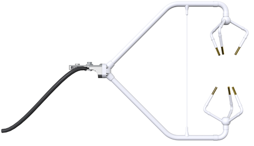
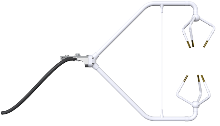
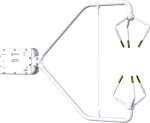
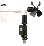
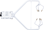
Der CSAT3-Anemometerkopf ist ähnlich dem Sensorkopf des CSAT3, aber das Kabel ist so angepasst, dass er an die Elektronik des EC100 angeschlossen werden kann. Er wird als Teil des EC150 und im CPEC200 Eddy-Kovarianzsystem verwendet.
Lesen Sie mehrFunktionen und Vorteile
- New conformal coating helps protect sonic transducers in corrosive environments
- Innovative design provides precision turbulence measurements with minimal flow distortion
- Usually combined with EC150 or EC155 gas analyzers giving near complete colocation for eddy-covariance measurements
- Compatible with most Campbell Scientific data loggers
- Measurements can be used to calculate momentum flux and friction velocity
- Campbell Scientific’s fine wire thermocouples are an option for fast-response temperature measurements
- Field rugged
- Innovative signal processing and transducer wicks considerably improve performance of the anemometer during rain events
- Sealed sonic transducers and electronics
Bilder
Zugehörige Produkte

Technische Beschreibung
The CSAT3A is an optional component of an EC150 open-path or EC155 closed-path CO2/H2O gas analyzer. It attaches to a common mounting bracket and connects to the gas analyzer's EC100 electronics module.
Kompatibel mit
Spezifikationen
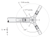
| Measurement Path Length |
|
| Path Angle from Horizontal | 60° |
| Construction | Sealed sonic transducers and electronics |
| Anemometer Head Materials | Stainless-steel tubing |
| Electronics Box Materials | Welded aluminum |
| Operating Temperature Range | -30° to +50°C |
| Voltage Supply | 10 to 16 Vdc |
| Current |
|
| Digital SDM Output Signal | CSI 33.3 k baud serial interface for data logger/sensor communication. (Data type is 2-byte integer per output plus 2-byte diagnostic.) |
| Support Arm Diameter | 1.59 cm (0.63 in.) |
| Transducer Diameter | 0.64 cm (0.25 in.) |
| Transducer Mounting Arm Diameter | 0.84 cm (0.33 in.) |
| Anemometer Head Dimensions | 47.3 x 42.4 cm (18.6 x 16.7 in.) |
| Anemometer Head Weight | 1.7 kg (3.7 lb) |
Measurements |
|
| Outputs |
ux, uy, uz, c (ux, uy, uz are wind components referenced to the anemometer axes; c is speed of sound.) |
| Speed of Sound | Determined from three acoustic paths; corrected for crosswind effects. |
| Measurement Rate | Programmable from 1 to 60 Hz, instantaneous measurements. Two over-sampled modes are block averaged to either 20 Hz or 10 Hz. |
| Output Bandwidths | 5, 10, 12.5, or 20 Hz |
| Output Rate | 10, 20, 25, or 50 Hz |
| Measurement Resolution |
|
| Offset Error |
|
| Gain Error |
|
| Rain | Innovative ultrasonic signal processing and user-installable wicks considerably improve the performance of the anemometer under all rain events. |
Digital USB and RS-485 Output Signal |
|
| Baud Rate | 230400 bps (maximum) |
| Data Type | Comma-delimited ASCII |
SDM, USB, & RS-485 Digital Outputs Reporting Range |
|
| Full-Scale Wind | ±65.535 m/s autoranging between four ranges (Least significant bit is 0.25 to 2 mm/s.) |
| Speed of Sound | 300 to 366 m/s (-50° to +60°C) Least significant bit is 1 mm/s (0.002°C). |
Dokumente
Broschüren Produkte
Handbücher
- EC150 CO2 and H2O Open-Path Gas Analyzer and EC100 Electronics with Optional CSAT3A 3D Sonic Anemometer - 900
- CSAT3 3-D Sonic Anemometer - 347
- Open Path Eddy Covariance System with IRGASON or EC150/CSAT3A Quick Deploy Guide
- EC155 CO2 and H2O Closed-Path Gas Analyzer and EC100 Electronics with Optional CSAT3A 3D Sonic Anemometer - 905
FAQs für
Number of FAQs related to CSAT3A: 22
Alle anzeigenWenige anzeigen
-
Campbell Scientific does not offer any mounting booms or hardware that enable easy and frequent positioning of the sonic anemometer sensor head. This type of hardware must be provided by the user.
-
The CSAT3A, CSAT3AH, CSAT3B, and CSAT3BH—like other sonic anemometers—measure wind speed along the sonic path using ultrasonic signals. If the salt spray blocks the sonic path, the sonic anemometer will not be able to make measurements. The same is true if a thick layer of salt is deposited on the transducer faces.
-
The sonic anemometer measures three-dimensional wind in a right-handed Cartesian coordinate system. From these measurements, use trigonometry to compute the wind flow angle, horizontal angle, and wind speed.
-
No. The offset is a function of temperature and time. Once a year, spot-check the sonic anemometer wind offset using the procedure outlined in the CSAT3B instruction manual. If the measured offset is outside the specification, return the sensor to the factory for calibration. To request a return material authorization (RMA) number, follow the steps listed on our Repair and Calibration page.
-
The CSAT3/3A/3AH calibration applies a correction for transducer delay over temperature. Transducer delays cause an offset in the wind speed measurement, and to a lesser extent, an offset in the speed of sound measurement.
The CSAT3/3A/3AH speed of sound easement is corrected for the effects of wind blowing normal to the sonic path.
-
Yes. If the matching layer is damaged or missing, return the sonic anemometer to the factory for repair. Follow the steps listed on our Repair and Calibration page to request a return material authorization (RMA) number.
-
No. The CSAT3/3A/3AH is a sensor. Time stamps are assigned to the sonic anemometer data by the data-acquisition system—typically a Campbell Scientific data logger or PC.
-
No. The sonic anemometer does not report time with the wind measurements. A time stamp will be assigned to the wind data by the data-acquisition system—either a data logger or a PC.
-
The sonic anemometer offset specification is ±8 cm/s. Therefore, it cannot be used in an application where the expected wind speed is in the range of ±5 cm/s.
-
Yes. The bubble level can be replaced in the field using pn 31962, 1-Ring Replacement Bubble Level with Mounting Bumper and Hardware.
Anwendungsbeispiele
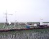
With instrumentation and help from Campbell Scientific, personnel from the Department of Atmospheric Sciences at......lesen Sie mehr