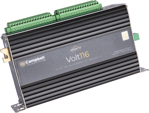
Überblick
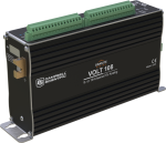
Das VOLT 116 ist ein analoges Eingangsmodul, mit dem man einen Campbell-Datenlogger einfach erweitern kann. Es hat sechzehn differentielle oder zweiunddeißig single-ended Eingangskanäle und vier Anregungskanäle. Angeschlossene Geräte können über zwei 12 V- und zwei geschaltete 12 -V Ports mit Strom versorgt werden, außerdem gibt es vier geschaltete 5 V -Ports zur Steuerung von Geräten. Das VOLT 116 verwendet einen 24-bit, AD-Wandler und hat sehr wenig Rauschen für bestmögliche analoge Messungen. Das VOLT116 unterstützt auch Period-average Messungen und bietet Anregungsstrom und -spannung.Funktionen und Vorteile
- 24-bit AD-Wandler und geringes Rauschen auf den Eingängen
- Erweiterung der analogen Kanäle über den CPI Bus
- Erhöht die Anzahl der Eingangskanäle aber nicht die Messzeit
- Einfacher zu programmieren als herkömmliche Multiplexer
- Rauschunterdrückung kann ausgewählt werden.
- CANbus 2.0 A/B Ausgabe möglich mit -XD Version
- USB 2.0 Anschluss zur direkten Verbindung mit dem PC
Bilder


Kompatibel mit
Please note: The following shows notable compatibility information. It is not a comprehensive list of all compatible products.
Datenlogger
| Product | Compatible | Note |
|---|---|---|
| CR1000X (retired) | Requires OS version 4 or greater. | |
| CR6 | Requires OS version 10 or greater. |
Miscellaneous
| Product | Compatible | Note |
|---|---|---|
| GRANITE 10 | Requires OS version 1 or greater. | |
| GRANITE 6 (retired) | Requires OS version 1 or greater. | |
| GRANITE 9 | Requires OS version 1 or greater. |
Additional Compatibility Information
The VOLT 116 is compatible with CPI-enabled data loggers only.
Spezifikationen
| Mounting | Standard 1-in. grid (DIN rail mounting available) |
| Operating Temperature Range |
|
| Power Requirements | 9.6 to 32 Vdc voltage |
| Accuracy |
|
| Number of Channels | 16 differential or 32 single-ended inputs |
| Analog Inputs | 32 single-ended or 16 differential (with ±5000 mV, ±1000 mV, ±200 mV ranges 24 bit ADC) |
| Maximum Scan Rate |
|
| Input Range | ±5000 mV, ±1000 mV, and ±200 mV |
| Period Averaging | Traditional period averaging on analog input channels |
| CPI | For data logger connection. Baud rate selectable from 50 kbps to 1 Mbps. (Allowable cable length varies depending on baud rate, number of nodes, cable quality, and noise environment, but can be as long as 700 m under proper conditions.) |
| USB | USB 2.0 full speed connection available for attaching to a PC. (Port is used to configure the module and download updates via our Device Configuration Utility.) |
| Warranty | One year against defects in materials and workmanship |
| Dimensions | 20.3 x 12.7 x 5.1 cm (8 x 5 x 2 in.) |
| Weight | 0.9 kg (1.95 lb) |
Typical Current Drain |
|
| Sleep | <1 mA |
| Active 1 Hz Scan |
2 mA (estimated) Assumes one single-ended measurement with the first notch frequency (fN1) at 30 kHz Note: Any sensor excitation or switched power loads will be additive to this value. |
| Active 20 Hz Scan |
20 mA Assumes one single-ended measurement with the first notch frequency (fN1) at 30 kHz Note: Any sensor excitation or switched power loads will be additive to this value. |
| Active 1 kHz Scan |
67 mA Note: Any sensor excitation or switched power loads will be additive to this value. |
Voltage/Current Excitation Outputs |
|
| Voltage Excitation | ±5 V (@ 50 mA) |
| Current Excitation | ±2.5 mA (±5 V compliance voltage) |
| Number of Voltage/Current Excitation Outputs | 4 |
General Purpose Outputs |
|
| Number of SW5V Outputs | 4 |
| SW5V Output Resistance | 30 Ω |
| Number of SW12V Outputs | 2 |
| Typical Limit of SW12V Outputs | 200 mA |
| Minimum Limit of SW12V Outputs | 180 mA |
| Number of 12V Outputs | 2 |
| Typical Limit of 12V Outputs | 200 mA |
| Minimum Limit of 12V Outputs | 180 mA |
Dokumente
Broschüren Produkte
Handbücher
Videos & Tutorials
Downloads
CPI Calculator v.1.0 (2.49 MB) 06-07-2016
The CPI Calculator is a downloadable Microsoft Excel spreadsheet used to estimate the usage and capacity of a CPI network. The calculator provides an overview on CPI devices including the CDM-A108, CDM-A116, CDM-VW300, CDM-VW305, and the CSAT3B. The calculator can also estimate the measurement speed of the CDM-A108 and CDM-A116 based on the number of channels and measurement parameters.
The CPI Calculator is an estimation tool and will help you better understand and design CPI networks by considering the following:
- What is the capability of each CDM or CPI device
- What is the CPI network capacity
- How much of the CPI capacity are the CDMs or CPI devices using
Volt100 OS v.06.03 (640 KB) 09-05-2023
Execution of this download installs the Volt108 / Volt116 Operating System on your computer which can then be uploaded to the Volt108 or Volt116 device with the Device Configuration Utility.
Liste der ÄnderungenFAQs für
Number of FAQs related to GRANITE VOLT 116: 8
Alle anzeigenWenige anzeigen
-
All outputs except strain gauge calculated microstrain are supported in CANOut:
- VOLT SE/Diff output in mV
- BridgeFull in mv/V
- BrHalf3W and BrHalf4W in Rs/Rf
- TEMP 120 output in desired temperature units
Note: Strain values are in mV/V and either need a data logger or post processing to calculate microstrain.
-
Yes, both 11-bit and the 29-bit (extended) message identifiers are supported.
-
in continuous scan mode (normal operation), 1 kHz on 1 channel is typical.
-
Only the XD versions (not the SD) support CANOut 2.0b. To enable this function, use our SURVEYOR software. When SURVEYOR recognizes an XD module, a CAN Enable menu appears with a “CAN Enabled” slider switch.
-
The VOLT 108/116 XD and TEMP 120 XD output CAN2.0b data frames in Big Endian byte format.
-
in Burst Mode operation, repeated measurements are performed on the same channel for X number of times, then there is a waiting period for the measurements to be processed and transmitted to the data logger. No measurements can be made during this processing period. The maximum capture rate is 30 kHz on a single channel for a duration of 2.18 seconds (absolute maximum capability).
-
Yes, a specific CAN ID can be selected for each module.
-
The CPI bus speed is adjustable in your CRBasic data logger program. Use the CPISpeed() instruction in your CRBasic program to adjust the CPI bus bandwidth to meet the following maximum combined (total) Ethernet cable lengths:
- 1000 kB/s for maximum combined Ethernet cable lengths of 15.2 m (50.0 ft)
- 500 kB/s for maximum combined Ethernet cable lengths of 61 m (200 ft)
- 250 kB/s for maximum combined Ethernet cable lengths of 152.4 m (500 ft)
Anwendungsbeispiele
Overview The Udhampur-Srinagar-Baramulla Rail Link (USBRL) project is of national importance as it connects Kashmir to the......lesen Sie mehr
China is making strides in the global wind energy market, especially when it comes to......lesen Sie mehr
Overview In the fight against climate change, innovative solutions are emerging to address the global challenge......lesen Sie mehr
