
durch patentierte VSPECT® Technologie


Überblick
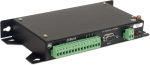
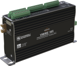
With an AVW200 vibrating wire analyzer module, your data logger can measure vibrating wire strain gages, pressure transducers, piezometers, tiltmeters, crackmeters, and load cells. These sensors are used in a wide variety of structural, hydrological, and geotechnical applications because of their stability, accuracy, and durability.
Learn about our patented VSPECT® spectral-analysis technology at our VSPECT® Essentials web resource.
The dynamic vibrating wire measurement technique is protected under U.S. Patent No. 8,671,758, and the vibrating wire spectral-analysis technology (VSPECT®) is protected under U.S. Patent No. 7,779,690.
Lesen Sie mehrFunktionen und Vorteile
- Provides better measurements by significantly reducing incorrect readings caused by noise sources
- Interfaces two vibrating wire sensors; more sensors may be connected if an AM16/32B multiplexer is used
- Self-checking diagnostics give continual feedback on sensor condition
- High resolution—less than 0.001 Hz (industry standard is 0.1 Hz)
- Low current drain
- Interfaces both temperature and frequency measurements from vibrating wire sensors
Bilder


3D/CAD-Dateien:
Technische Beschreibung
The AVW200 uses vibrating wire spectral-analysis technology (VSPECT®). VSPECT® observes the incoming sensor signal, performs a Fourier transform and a spectral analysis (transforming the time series into individual sinusoidal components in the frequency spectrum), and determines the sensor frequency by identifying the largest signal in the acceptable range while filtering out environmental and electrical noise.
The AVW200 analyzer module also provides many self-checking diagnostics such as vibrating element signal strength, signal-to-noise ratio, vibrating element signal decay ratio, and incorrect signal response. These diagnostics can be running in the background to give continual feedback of the condition for each sensor.
Kompatibel mit
Please note: The following shows notable compatibility information. It is not a comprehensive list of all compatible products.
Datenlogger
| Product | Compatible | Note |
|---|---|---|
| CR1000 (retired) | ||
| CR1000X (retired) | ||
| CR1000Xe | ||
| CR200X (retired) | ||
| CR216X (retired) | ||
| CR300 (retired) | ||
| CR3000 | ||
| CR310 | ||
| CR350 | ||
| CR5000 (retired) | The CR5000 supports the SDI-12 mode only. | |
| CR6 | The CR6 is compatible with the AVW200. However, because the CR6 has built-in vibrating wire measurement capabilities, the AVW200 is unnecessary. | |
| CR800 (retired) | ||
| CR850 (retired) | ||
| CR9000X (retired) |
Halterungen und Masten
| Product | Compatible | Note |
|---|---|---|
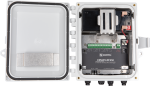
| ENC10/12 | If using the RS-232 port, the AVW200 must be mounted flat to fit in an ENC10/12. | |
| ENC12/14 | If using the RS-232 port, the AVW200 must be mounted flat to fit in an ENC12/14. | |
| ENC14/16 | ||
| ENC16/18 |
Additional Compatibility Information
Sensors
The AVW200 Vibrating Wire Spectrum Analyzer Module allows our data loggers to measure vibrating wire strain gauges, pressure transducers, piezometers, tiltmeters, crackmeters, and load cells.
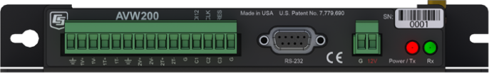
Data Logger Connections
When using SDI-12, a three-conductor cable is required; Campbell Scientific recommends the CABLE3CBL-L cable. When using RS-232, the module attaches to the data logger’s RS-232 port via the 18663 null modem cable, or attaches to control ports on a CR800, CR850, CR1000, or CR3000 datalogger via the 17855 data cable.
Enclosure Considerations
The AVW200 requires a desiccated, non-condensing environment. A Campbell Scientific enclosure is recommended when the analyzer module is in the field. The AVW200 has built-in keyhole flanges for mounting to an enclosure backplate.
Power Considerations
The AVW200 is typically powered by the data logger's power supply.
Spezifikationen
| -NOTE- | Electrical specifications are valid over a -25° to +50°C range unless otherwise specified. Non-condensing environment required. |
| Number of Vibrating Wire Sensors Measured | Up to 2 vibrating wire sensors can be connected to the analyzer module. Additional sensors can be measured by using an AM16/32-series multiplexer. |
| Power Requirements | 9.6 to 16 Vdc |
| Analog Input/Outputs | 2 differential (DF) vibrating wire measurements (V+ and V-) and 2 single-ended (SE) ratiometric resistive half-bridge measurements (T+ and T-) for vibrating wire sensor's onboard temperature sensor. |
| Digital Control Ports |
3 digital control ports (C1 – C3)
|
| RS-232 Port | 1 9-pin RS-232 port (for connecting to a data logger COM port) |
| Measurement Resolution | 0.001 Hz RMS (±250 mV differential input range; -55° to +85°C) |
| Measurement Accuracy | ±0.013% of reading (±250 mV differential input range; -55° to +85°C) |
| Input Voltage Range | ±250 mV (differential) for vibrating wire inputs |
| Common Mode Range | ±25 V |
| Baud Rates | Selectable from 1200 to 38.4 kbps. (ASCII protocol is one start bit, one stop bit, eight data bits, and no parity.) |
| Memory |
|
| CE Compliance Standards to which Conformity Is Declared | IEC61326:2002 |
| Dimensions | 21.6 x 11.18 x 3.18 cm (8.5 x 4.4 x 1.25 in.) |
| Weight | 0.43 kg (0.95 lb) |
Typical Current Drain @ 12 Vdc |
|
| Quiescent, Radio Off | ~0.3 mA |
| Radio Duty Cycling 1 s | ~3 mA (includes quiescent current) |
| Radio Always On | ~26 mA (radio transmit current 100 mA) |
| Active RS-232 Communication | ~6 mA (3 s after communication stops, the current will drop to the quiescent current.) |
| Measurement | ~25 mA (averaged over the 2 s) |
Dokumente
Realisierte Projekte
Übereinstimmung mit Richtlinien u. Vorschriften


Downloads
AVW200 OS v.06 (551 KB) 10-06-2016
Current AVW200 firmware. Use the Device Configuration Utility version 1.13 or greater to send firmware and to configure the AVW200.
AVW200 Program Examples v.1 (8 KB) 31-01-2025
Example programs for the AVW200 and AVW206. The examples demonstrate a direct RS-232 connection to the AVW200, a wireless connection to an AVW206, an SDI-12 connection to the AVW200 and using multiplexers with the AVW200.
FAQs für
Number of FAQs related to AVW200: 9
Alle anzeigenWenige anzeigen
-
The AVW200-series modules are not required, but they do reduce the chance of erroneous readings by filtering electrical noise that is sometimes present.
-
The AVW200 must be wired directly to the datalogger via a cable.
The AVW206, AVW2011, and AVW216 have built-in spread-spectrum radios tuned to different frequencies that allow the datalogger to communicate with a remote AVW device through an appropriate radio link.
-
Two probable causes are the following:
- The SerialOpen() instruction has not been added to the datalogger code.
- The correct PakBus address setting has not been used in the AVW200 instruction.
-
It takes 2 s for the AVW200-series modules to acquire a measurement from each sensor. An AVW200-series module servicing two AM16/32B multiplexers, each with 16 vibrating wire sensors, requires approximately 64 s to acquire data.
-
Yes, using a null modem cable.
-
Use pn 17855, Data Cable, RS-232 Male to Pigtail.
-
Dozens of AVW200-series modules can be accessed through one CR1000. The limiting factor is the frequency at which the CR1000 is set to retrieve data from each module. If the CR1000 needs to collect data very frequently from the modules, fewer AVW200-series modules can be accommodated in the time between data collection events.
-
Two multiplexers, each with a maximum of 16 or 32 sensors per multiplexer, can be attached. If temperature measurements are excluded from each sensor, 32 sensors are possible.
Anwendungsbeispiele

In 2022, as Hurricane Fiona unleashed relentless rain on Puerto Rico, the Puerto Rico Landslide......lesen Sie mehr

The Homestake Neutrino Experiment—also referred to as the “Davis Experiment” after physicist Ray Davis, who......lesen Sie mehr

Background In 2022, ECR Medio Ambiente assumed the responsibility of overseeing the structural monitoring installation at......lesen Sie mehr
RESPEC, a water-resources consulting and services firm, is currently under contract to operate and maintain......lesen Sie mehr
The Utah Department of Transportation is investigating the effect on the life span of bridges......lesen Sie mehr

On August 1, 2007, the I-35W St. Anthony Falls Bridge over the Mississippi River in......lesen Sie mehr